

Ian spotted a picture of the Hirondelle in a ‘SAMS’ catalogue and produced his plans from a small drawing. The aircraft was selected because as a monoplane it was a nice compliment to his Tabloid and Avro triplane. The model construction began at the end of October 1993 and was completed mid February 1994.
From the initial drawings some small changes were made to make assembly of the model at the field easier. The tail position was raised and the wing section was changed to enable two ribs to be cut from a 36″ x 4″ x 3/16″ balsa sheet.
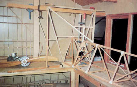
The fuselage was made by first building the top horizontal outline. Longerons were made from clear Columbian pine approximately 14mm square at the nose tapering to 9mm square at the tail. The Hirondelle has a short nose and long fuselage hence the tapering of the longerons. Temporary ply jigs were made and nailed to the building board to hold the bottom longeron in position. Uprights and diagonals were then cut and fitted.
Uprights and diagonals were carved to a triangular section, but leaving the wood square at the joint with the longerons. This carving saved about 4 ozs in weight and hence approximately 1 1/2 lbs in nose ballast. All the joints were reinforced with 1/32″ ply gusset plates. The forward fuselage sides and top decking were constructed from 1/32″ ply. Exterior grade PVC glue used for construction of the wooden components.
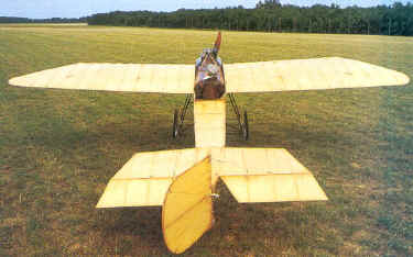
In the tailplane, similar weight saving techniques were employed. The tailplane and elevators had a 55″ span and weighed 19ozs.
The rudder has a laminated outline made from strips of 1/16″ ply. The rudder post was made from two pieces of half round dowel glued together. Hinges were made from stainless steel straps over PTFE bushes.

The wings use two plank spars and together with the leading and trailing edges were made from clear Columbian pine. Ash blocks were fitted at the wire attachment points with 1/16″ ply either side of the spars. The wings are mounted on 6 gauge piano wire rods. 1/4″ stainless steel tubes were glued into blocks which were then glued and bound to the roots of the wing spars.
The rear skid is made from laminations of ash bolted to the reinforced bottom longeron with alloy plates. The undercarriage is also from ash. This is a feature of the plane and required 27ft of ash to complete! This was made as thin as possible, but even so weighs about 44ozs. Stainless steel brackets were designed using cardboard templates. These were cut out and fitted to the model with 3mm bolts.
Before covering the wood it was protected by a thinned coat of Solarlac varnish. Balsarite was applied to all the outlines and wing ribs to aid the adhesion of the Polytex covering. The ply covering was stained a dark colour with Ronseal stain and finished with several coats of gloss varnish.
The fabric surfaces were weathered with a variety of coloured varnishes and protected with a semi-matt polyurethane varnish.
The wheels are 14 1/2″ diameter cycle wheels on a 10mm EN24T steel axial. Cycle cones and 1/8″ ball bearings were fitted and the suspension is bungee rubber.
To save making hatches, the rudder and elevator servos are placed directly behind the engine firewall. The wing warp servo was made accessible via the cockpit.
A dummy engine was made from a ply box with ply fins, the King cylinder being in-front of this. Throttle and choke servos are mounted inside the dummy cylinder and directly in-line with the engine’s carburetor.
The pilot is essential, but is a long way behind the center of gravity and so care was necessary to avoid weight. The pilot was made from an amalgamation of a 1/2 size AH pilot with his upper torso dismembered and reconstructed larger. A 1/2 size Pete’s Pilot head was then grafted on. Ian says that he and his wife felt a bit like Dr Frankenstein and his assistant during this major surgery!
The radio used is Futaba 1024 PCM. The elevator and rudder servos are S3303’s and the warp servo an industrial Simprop unit. The receiver is between the pilot’s knees, well away from the possibility of interference from the engine. Two flight batteries, the ignition and warp servo batteries are mounted below the engine.
The model needed about 1lb of lead in the nose to bring the balance point to 30% of the wing cord.

The wing and undercarriage wires use 49 strand, 1.5mm diameter stainless steel. The rudder and elevator control cables are 100lb fishing trace wire.
The wing incidence is about 2 1/2 degrees with a touch of washout. The warp movement at the outer rib is about 1 1/2″ up and down. The tail incidence is set at zero degrees and the engine has 1 degree of right thrust.


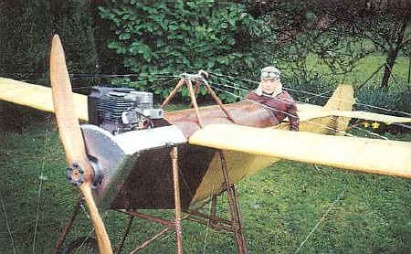
Ian thought that his King 100cc engine with a reduction drive would be a good match. The reduction unit was designed by Ian and was an interesting part of the model’s development. This has resulted in a great sounding engine resembling a typical early engine.
Assembly time is about 15 minutes. The tail has a ply tongue at the front and two 3mm Allen screws at the rear. There is a 3mm Allen screw for the bottom rudder hinge plus another 3mm Allen screw for the tailplane struts. The wings have 16 wires fitted with 3mm Allen screws via turnbuckles and stainless steel wing plates.
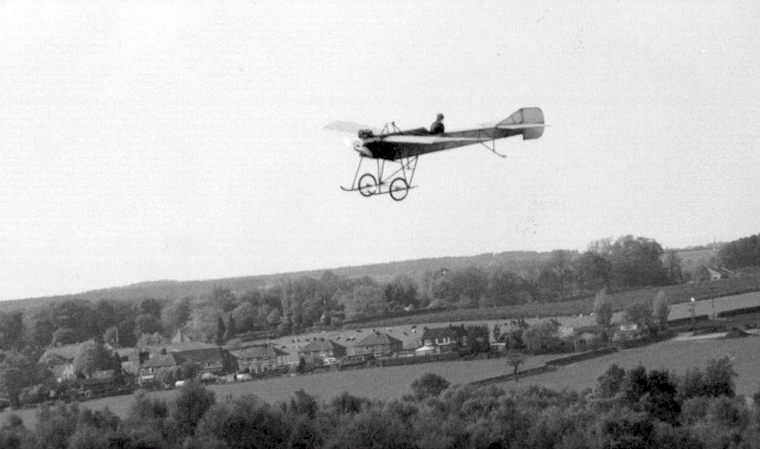
The first flight was made 25th February 1994. Some right rudder trim was introduced to compensate for the anticipated torque reaction. the Hirondelle tracked straight, but once in the air wanting to turn right. The wing warping is not very effective, but by applying rudder first, and then warp control (to balance the turn) reasonable turns can be made. The rudder are elevator are responsive. The climb is not brilliant, but acceptable.
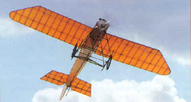
Overall, the model is very stable and flies well. Landings are easy, but require a powered approach.
For event tickets, merchandise and more visit our online shop.