The full-size aircraft began as an improvisation forced upon the Bristol design staff in the wake of the Munich crisis of 1938. The Mark I began as a Home Defence Night Fighter, but this was soon extended to long-range escort fighter and ground attack duties which were urgently needed. It was adapted to many other duties including those of bomber, torpedo-carrier and rocket fighter. The Australian Beaufighters which blasted Japanese naval and merchant ships resulted in the aeroplane being given the nickname ‘Whispering death’. After the war many were converted to target tugs. The last was withdrawn from service in 1960.
The 14′ 5″ (4.40m) wingspan model weighs 120lbs (54.4kg). It was built to the design of the famous MB-T ‘Tommy’ (NT950) of 236 Squadron, Coastal Command. The model is 10′ 8″ long and 3′ 10″ high.
The engines are: 2 x 120cc horizontally-opposed twins (3W). There are two, 2 litre tanks (petrol, 50:1 two-stroke). The propellers used have been: 30″ x 10″ (two-blade); 28″ x 12″ (three-blade).
It took 3.5 years (approximately 2500 hr) to complete the model. It was first flown in April 1998 and between then and its sad demise at the Cosford 2002 show had approximately 140 flights.

Taxing out for another flight.
The electrical system was designed using a star based distribution system. The distribution board was provided with common power lines and tracks to connect the receiver signal to the servos. Battery supply leads were connected to the power rails and were used to feed the servos. The receivers had individual supplies. To add a further failsafe function the PPM receiver signals were fed through a CMOS OR gate. A failsafe was also incorporated from Mainlink.
Seventeen servos were used. Multiplex ‘Power’ servos were used on the evelators, Futaba giant servos on the rudder and ailerons and eight Futaba 9202’s on the four flap sections. The other functions used standard servos.
A piezoelectric gyro was connected to the rudder circuit to cope with yaw asymmetries.
A schematic diagram of the system is shown below.

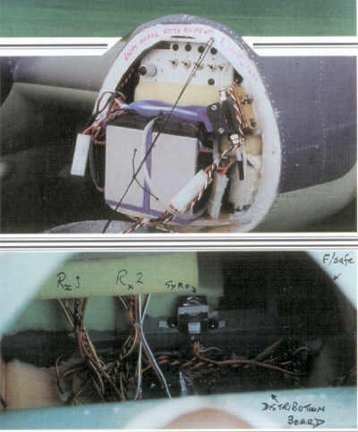
The batteries used are: a 4 Ahr and two 10 Ahr 6 volt Yuasa main packs, two 700mAhr Rx packs, a 13.2 volt landing-light pack and two 1400mAhr ignition packs. This provided plenty of power for a weekend’s flying and also helped with nose weight. Some of these batteries can be seen in the top photograph. Note that the cheap connectors seen are only used for the charging and auxiliary circuits. The switches shown are for the receivers, servo power and auxiliary circuits. The in-built monitor and LEDs and the pneumatic spool valve for the undercarriage can also be seen.
The bottom photograph is from just behind the cockpit. It shows the receiver locations in the top of the fuselage. All the units were foam mounted to isolate them from vibration. The distribution board is at the bottom of the fuselage and you can see the twisted wire connections. The gyro is mounted in the centre on the mainspar.

For event tickets, merchandise and more visit our online shop.